 page 3
HENRY 2K-3 Kilowatt Linear
Amp
- Rebuild by WB2GCR
As I was saying, the next area that I
looked at was the Power Supply. The power supply
sits in the bottom of a cabinet, the
RF deck sits into the top.
It seemed to be in pretty good shape.
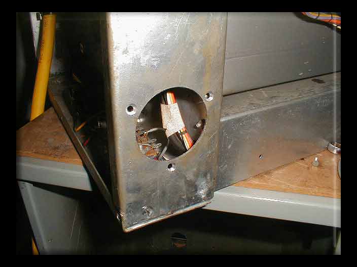
But the AC mains wire was pretty ratty, and it was
routed through a hole in the chassis,
with a grommit that was long gone, and hung inside right
on top of the HV wires. I also found
the nuts on the caps to be loose. Tightened them gently.
The plate meter is hung off the bottom
of the HV bridge rectifer across a 50 Ohm resistor.
There it was, but no rating on it, and
I had no PS schematic. Also it was open.
Major thanks to Alan, AD6MT who came through
with a complete copy of the schematics and
manual! So, I now knew it was supposed
to be a 50 ohm 25 watt resistor. I hung in a 46.5 ohm
and a 3 ohm and called it a day! You
can see the two in the photo below.
The wires between the HV rectifier blocks
also needed resoldering... they were hanging on thin
bits of solder, tacked on.
Back to the power cord, it had been 12ga
x 3. I grabbed some 10ga x 3 in nice yellow neoprene
insulation and fabbed a short length
and determined to put a nice TWISTLOC power connector
where the grommit hole had been! Might
as well do it right!
Here it is:
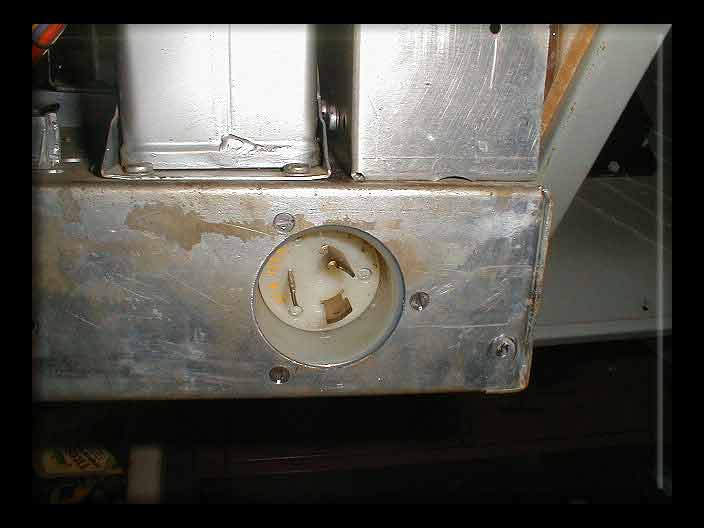
Then in goes the twistloc:
Here's the bottom with the re routed power
cord, sitting on standoffs now:
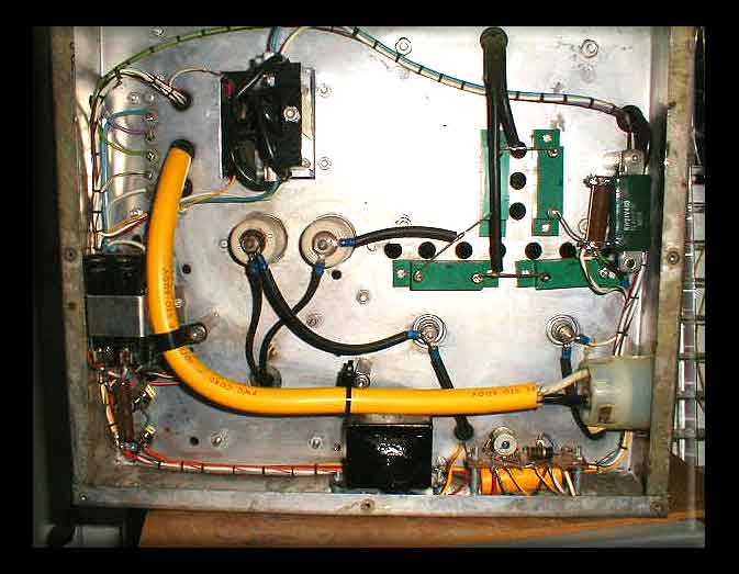
Ok, it's not my layout! It's 1972 Henry, whaddya expect?
Did I mention that it is missing the bottom
plate too? Gotta make one up... I intend to put the unit on
casters so that you can move it around
and permit some cooling up through the bottom of the power
supply unit...
That and more is coming soon! All this
and it still isn't running and hasn't been fired up. Next after
the bottom plate and casters is the front
panel, new knobs, mounting the meters, the new SWR pot,
and LEDs for lighting the dials! :- )